Installation
InstAllation
In assembly, where more than one shaft is used, the second or succeeding shafts become redundant for guidance. Unless "perfect alignment" of the shafts (parallelism, not angularity) exists, a misaligned shaft will add a preload to the bearing and restrict the normally smooth and easy motion. The ideal shaft mounting arrangement is shown in Figure 1. Here one shaft is fixed and guides the system while the second or succeeding shafts "float" and are only load-carrying members.
Another cause of restricted motion is "bore in accuracy." The bearing mounting hole should have a maximum diameter so that there is, at least, a line to line fit between the outside diameter of the bearing and the hole. A press fit (though not recommended for any linear bearing) transmits the press to the shaft and bearing clearance, creating a preload. Unknown in quantity of pounds (kilograms), this could shorten the life cycle of the system greatly. If a press is mandatory, the solution is to choose a larger than normal clearance between the diameter of the shaft end bearing. This offers a safety margin.
The linear rotary bearing, by its inherent design of no inner race, is most susceptible to local contamination. The design features an optional integral seal. Here the contaminants are wiped free of the ball track system by cleansing the entering surfaces of the shaft.
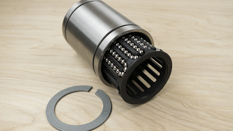
The basic methods of mounting the linear rotary bearing are external and internal. For external mounting, there are retaining ring grooves on the exterior surface of the bearing. These grooves accommodate standard retaining rings, a typical arrangement is shown in Figure 2. Internal arrangements are shown in Figures 3 and 4. Figure 3 illustrates the internal retaining rings at each end of the bearing. Figure 4 shows the use of cover plates at each end of the assembly. If more than one bearing is used, a spacer maybe inserted to secure the overall precise fit. Another means of installation is to coat the bearing with an adhesive (carefully covering the bearing innards) and to insert it into the mount.
To sum up, all means of canceling error (tolerance and misalignment) should be incorporated into the design of systems utilizing the linear rotary bearing.

Figure 1

Figure 3

Figure 2

Figure 4